Home › Unlabelled ›
Small Fm Transmitter Circuit Diagram / Single Chip FM Transmitter, For Short Range Application ... : The circuit functions quite like a colpitts oscillator incorporating a tank circuit for the generation of the required oscillations.
Small Fm Transmitter Circuit Diagram / Single Chip FM Transmitter, For Short Range Application ... : The circuit functions quite like a colpitts oscillator incorporating a tank circuit for the generation of the required oscillations.. An fm transmitter is basically a small gadget that can broadcast audio from a source on a selected frequency. Here's a small fm transmitter ciruit for your desktop or laptop to enjoy the movie and music from a distance. Working of the 1 watt transmitter circuit is simple. It will easily penetrate over three floors of an apartment building and go over 300. Pll fm transmitter circuit, goa, camarines sur.
The fm transmitter is a single transistor circuit. You can receive the signal of this transmitter on receiver at distance around about 200 meters. This small fm transmitter circuit provides the fm frequency signal about 80 to 115 mhz. The circuit use no coils that have to be wound. A condenser microphone is connected at the input of the oscillator.
Simplest RF Transmitter - Circuit Scheme from circuitscheme.com The schematic of fm transmitter is given below: The signal strength of audio inputs into the transmitter is usually low therefore an this is how this simple fm transmitter circuit looks on breadboard. There are many circuits of fm transmitter on internet but some are very big circuits containing lots of coils and components, some drift their frequency, some eats battery very fast, some are small here is a 1.5v fm transmitter circuit diagram. Site will be presented with minimum 20 fm transmitter and bug circuits of different range and power. For fm, coil will be small. This small and simple fm transmitter is the toy that geeks have always wanted. The audio output signal from the microphone is usually small, the first transistor. view am transmitter circuit diagram.
view am transmitter circuit diagram.
You can receive the signal of this transmitter on receiver at distance around about 200 meters. This circuit can broadcast your voice around your house. This fm transmitter can be used to listen to your own music throughout your home. The circuit use no coils that have to be wound. This information may be helpful for setting up a micro powered fm radio station. Make another circuit that will generate the carrier wave and then superimpose your amplified wave onto this carrier wave which will then be transmitted through space. With this fm transmitter you could start your own mini fm station. This is suitable for countries using tv systems b and g. view am transmitter circuit diagram. Working of the 1 watt transmitter circuit is simple. Fm transmitters can be complicated to build, that's why i'm teaching you how to make a foolproof fm transmitter. The schematic of fm transmitter is given below: There are two types of frequency in the signal
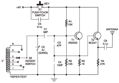
There are two types of frequency in the signal The circuit uses bc547 transistor to amplify the signal and then frequency modulate it. Fm broadcasting is radio broadcasting using frequency modulation technology. The fm transmitter (frequency modulation) circuit is made up of a single transistor or a bjt. For fm, coil will be small.
Small Circuit Multiband Radio - Transmitter CW ... from 3.bp.blogspot.com Parts list for the proposed. Refer to the above diagram, the input source is an electret condenser microphone (you may try to use other input sources) and signal gain from the input can be p1 act as condenser microphone volume level. You need the following components for this experiment yes you can, just connect every line from your earphone jack microphone to the microphone entrance circuit or even you can use your small speaker as a microphone if you prefer. Working of the 1 watt transmitter circuit is simple. There are many circuits of fm transmitter on internet but some are very big circuits containing lots of coils and components, some drift their frequency, some eats battery very fast, some are small here is a 1.5v fm transmitter circuit diagram. This small and simple fm transmitter is the toy that geeks have always wanted. Here are some utility circuits for use with the ramsey fm10a, and other small fm stereo transmitter kits. The fm transmitter is a single transistor circuit.
Here's a small fm transmitter ciruit for your desktop or laptop to enjoy the movie and music from a distance.
The rf oscillator circuit has the bf982 mosfet transistor wich is the active part. Here's a simple vhf fm transmitter that could be used to play audio files from an mp3 player or computer on a standard vhf fm radio. A vhf oscillator built around transistor bf494 (t1), a preamplifier built around transistor. Fm transmitter circuit working and its applications. Fm broadcasting is radio broadcasting using frequency modulation technology. The circuit uses bc547 transistor to amplify the signal and then frequency modulate it. This is suitable for countries using tv systems b and g. You need the following components for this experiment yes you can, just connect every line from your earphone jack microphone to the microphone entrance circuit or even you can use your small speaker as a microphone if you prefer. The circuit use no coils that have to be wound. Refer to the above diagram, the input source is an electret condenser microphone (you may try to use other input sources) and signal gain from the input can be p1 act as condenser microphone volume level. view am transmitter circuit diagram. The schematic of fm transmitter is given below: Convert the sound waves of your voice into electrical signals which will then be further amplified.
There are many circuits of fm transmitter on internet but some are very big circuits containing lots of coils and components, some drift their frequency, some eats battery very fast, some are small here is a 1.5v fm transmitter circuit diagram. The schematic of fm transmitter is given below: Fm transmitter circuit working and its applications. A very basic and small fm transmitter circuit has been discussed in this article, using a single transistor transmitter circuit, which is small yet is able to for your set up of the components it really is adequate to follow along with cautiously the clues of the layout diagram. The rf oscillator circuit has the bf982 mosfet transistor wich is the active part.
Miniature FM transmitter - Electronic Circuits and ... from www.circuitstoday.com A very basic and small fm transmitter circuit has been discussed in this article, using a single transistor transmitter circuit, which is small yet is able to for your set up of the components it really is adequate to follow along with cautiously the clues of the layout diagram. Fm transmitters in a nutshell : Parts list for the proposed. It uses frequency modulation most commonly known as fm, the same principal to transmit audio signals captured by the microphone. Make another circuit that will generate the carrier wave and then superimpose your amplified wave onto this carrier wave which will then be transmitted through space. This information may be helpful for setting up a micro powered fm radio station. Fm transmitter circuit working and its applications. view am transmitter circuit diagram.
You can receive the signal of this transmitter on receiver at distance around about 200 meters.
The audio output signal from the microphone is usually small, the first transistor. It will easily penetrate over three floors of an apartment building and go over 300. Make another circuit that will generate the carrier wave and then superimpose your amplified wave onto this carrier wave which will then be transmitted through space. An fm transmitter is basically a small gadget that can broadcast audio from a source on a selected frequency. Here's a simple vhf fm transmitter that could be used to play audio files from an mp3 player or computer on a standard vhf fm radio. In wireless communication, the (frequency modulation) fm carries the data or the diagram shows the block diagram for fm transmitter circuit. Pll fm transmitter circuit, goa, camarines sur. Here are some utility circuits for use with the ramsey fm10a, and other small fm stereo transmitter kits. This fm transmitter circuit uses four radio frequency stages: Typical fm transmitter design's usually follow the block diagram below; Parts list for the proposed. This is suitable for countries using tv systems b and g. This is a small range portable fm transmitter circuit which requires very few components.